Furata Pendulum
I've set out to design and build a custom desktop Furata Pendulum
A Furata Pendulum, otherwise known as a rotary inverted pendulum, is a device which consists of a driven base which rotates about the vertical axis, and a freely swinging pendulum attached such that the base rotation can balance the pendulum in an upright position.
Project Goals
My goal for this project is to design and build a compact, desktop Furata Pendulum based on an ESP32. I’ve laid out the following requirements:
- Stay within a budget of $150
- Must balance effectively, balancing motion should be minimal and smooth
- Final design should be compact and aesthetic
- Must be quiet enough to not be annoying
- Utilize an ESP-WROOM-32 Dev board (I had an extra one lying around)
- Not a requirement: Would be nice to develop a user interface to adjust system parameters once it is functioning
I think this project will present a rich learning opportunity in the field of control systems which I am beginning to learn, and what better way to learn than with a hands-on project!
Stage 1: Design and Parts
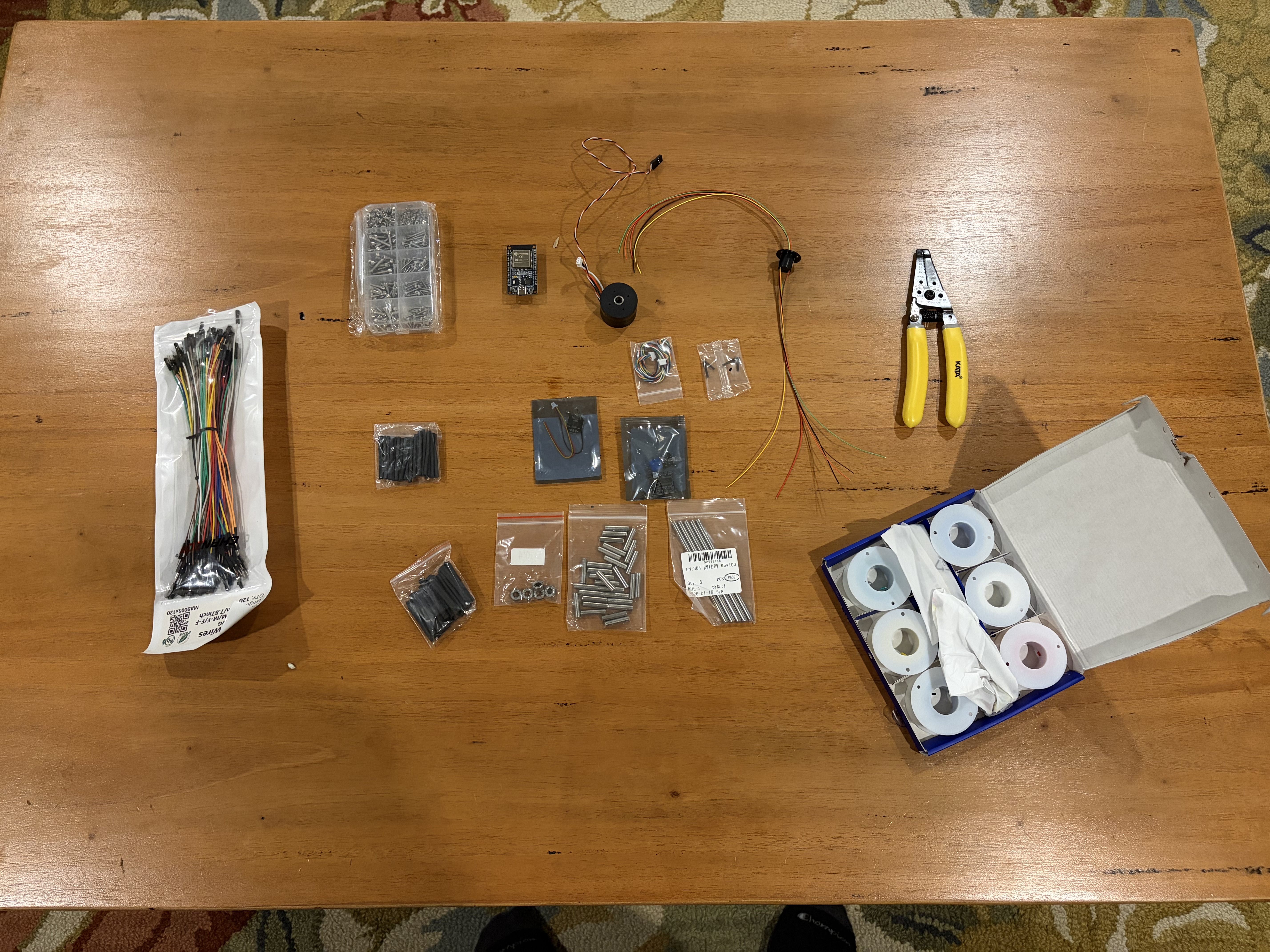
To begin the design, I tabulated all the components I will need to build the system. Below is a list of all the parts I sourced:
| Part Name | Description | Cost $(CAD) | Qty | | :— | :— | :— | :— | | Microcontroller | ESP-WROOM-32 | n/a | 1 | | Power Supply | 12V USBC Module | 1.63 | 1 | | Power Switch | JR223B Induction Capacitive Switch | 5.41 | 1 | | Voltage Regulator | Step down buck converter | 2.50 | 1 | | Motor Driver | DRV8313 SimpleFOC Mini | 6.61 | 1 | | Motor | GM2804 motor + AS5048A Encoder | 52.38 | 1 | | Encoder | AS5048A | 11.59 | 1 | | Slip Ring | 6 channel | 12.09 | 1 | | Frame/Base | 3D Printed frame | n/a | 1 | | Wire Terminals | JINH CMK633 | 5.33 | 1 | | Fasteners | SHCS M2, M3 620pcs kit | 13.79 | 1 | | M5 Steel Rods | 30x 22mm, 5x 100mm | 14.02 | 1 | | Shrink tube | Shrink tube 127pcs bag | 3.30 | 1 | | Bearings | Ball bearings, 5pcs | 3.33 | 1 | | Wire | 20awg wire rolls, 6 colour, 10ft ea | 20.04 | 1 | | Total Cost: $152.02 | | | |
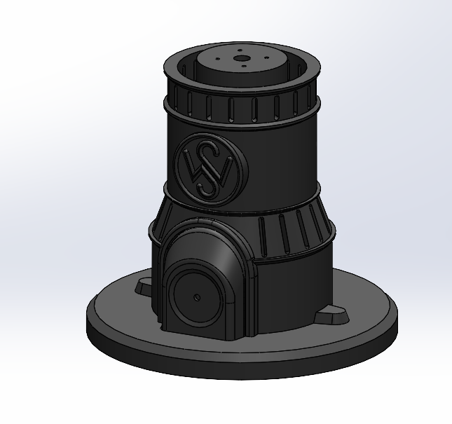
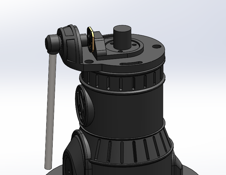
I chose to hit SolidWorks and try making a rough design to get an idea of how it will look and function.
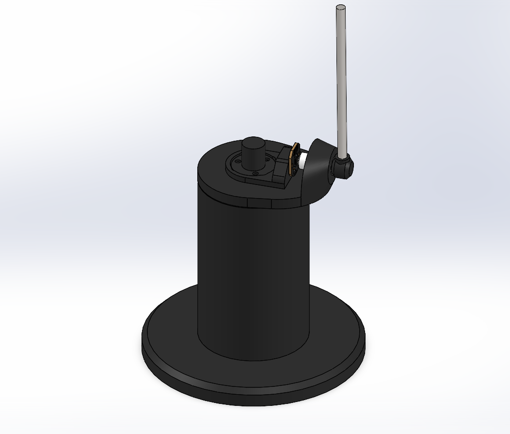
This rough form factor meets my requirement for compactness at a total height of only 220mm to the top of the pendulum.
While hashing out the initial design, I had to consider a few functional requirements. I quickly realized that the wires from the top encoder would twist relative to the fixed base — the two solutions for this would be to either restrict the rotation of the base, or to implement a slip ring, allowing the wires to rotate freely. I chose to use a slip ring.
With that sorted, the initial design felt solid enough to start ordering parts and move forward.
Stage 2: Electronics Capsule Design and First Motor Test
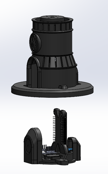
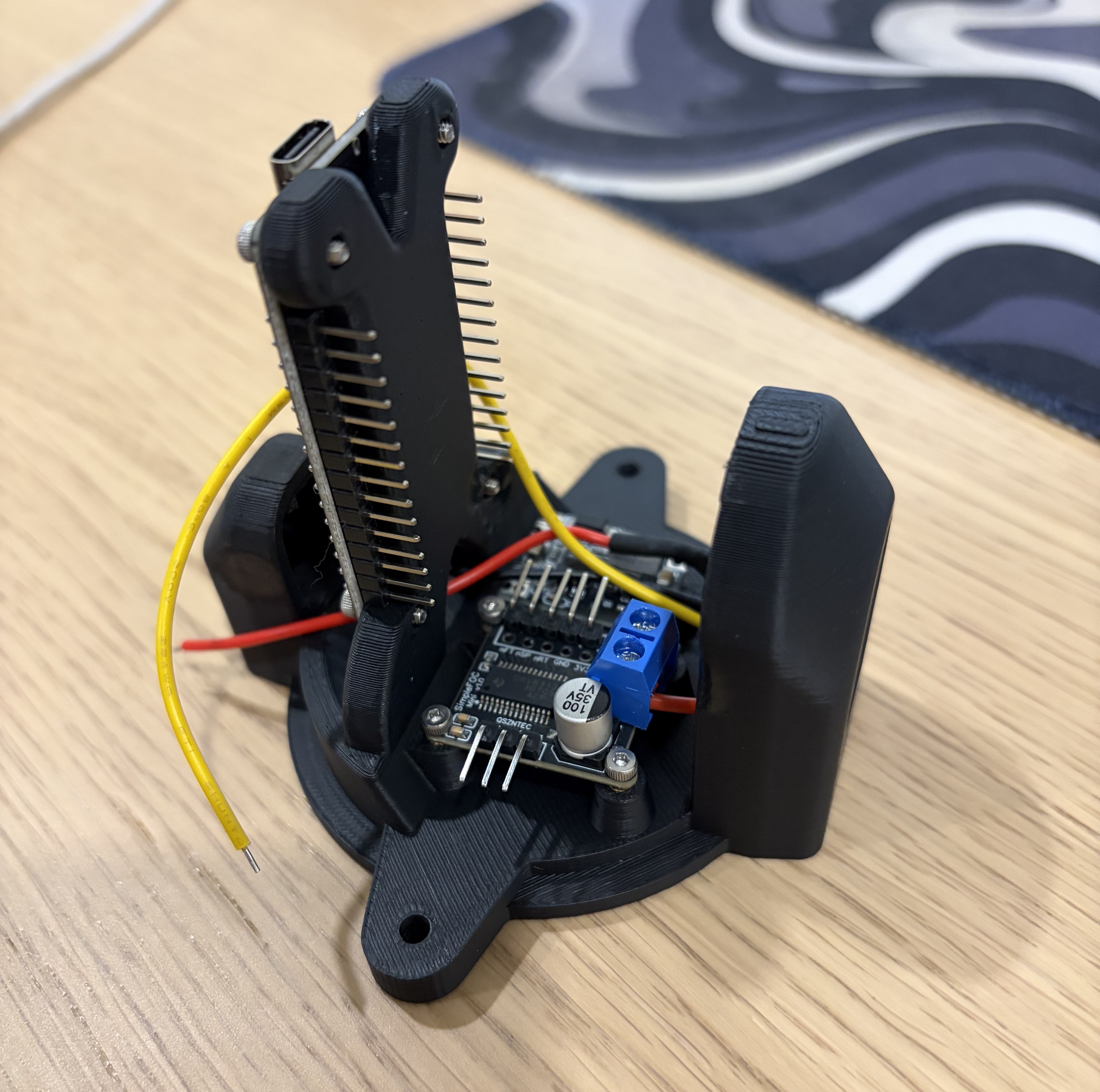
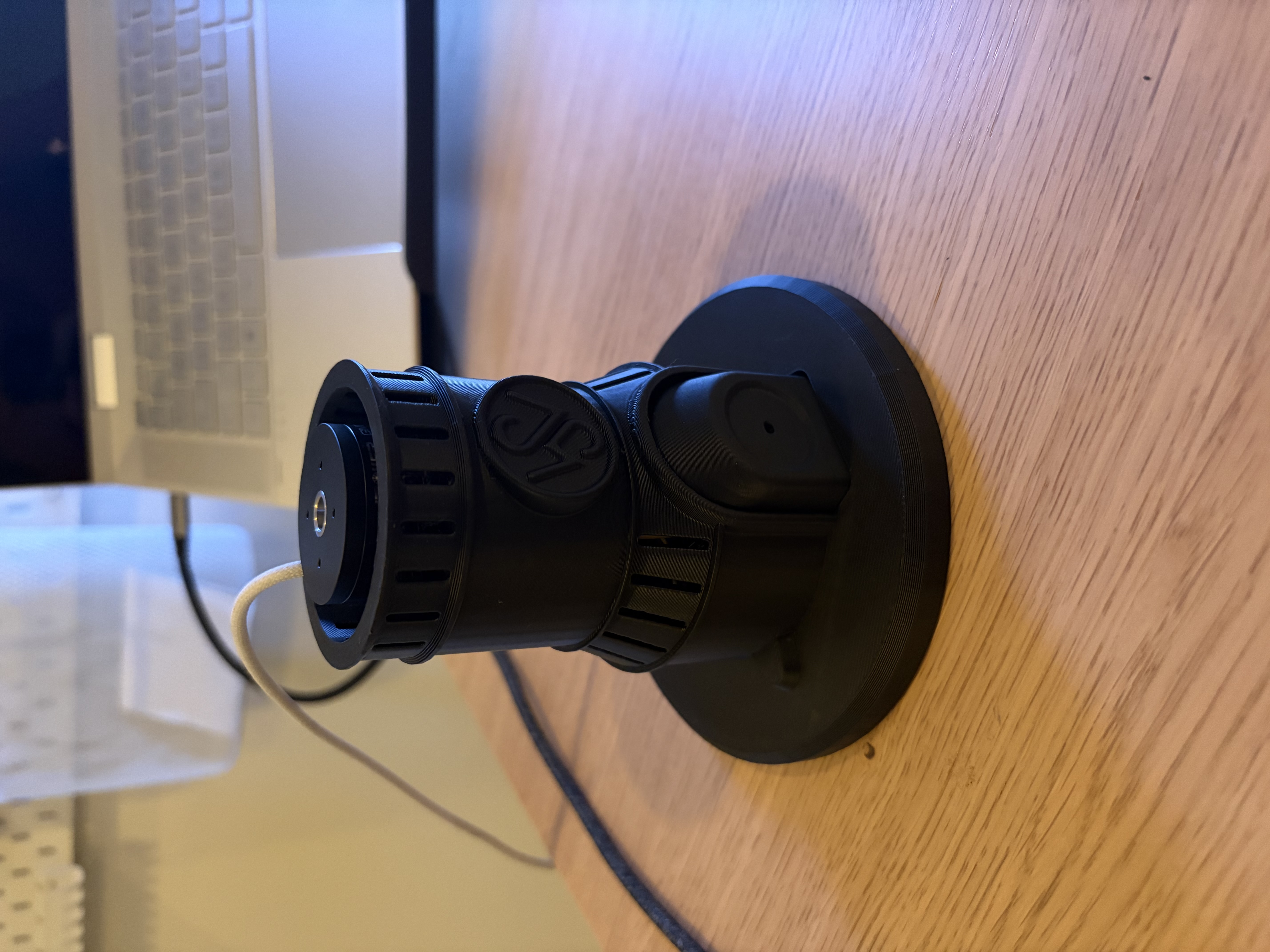
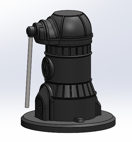
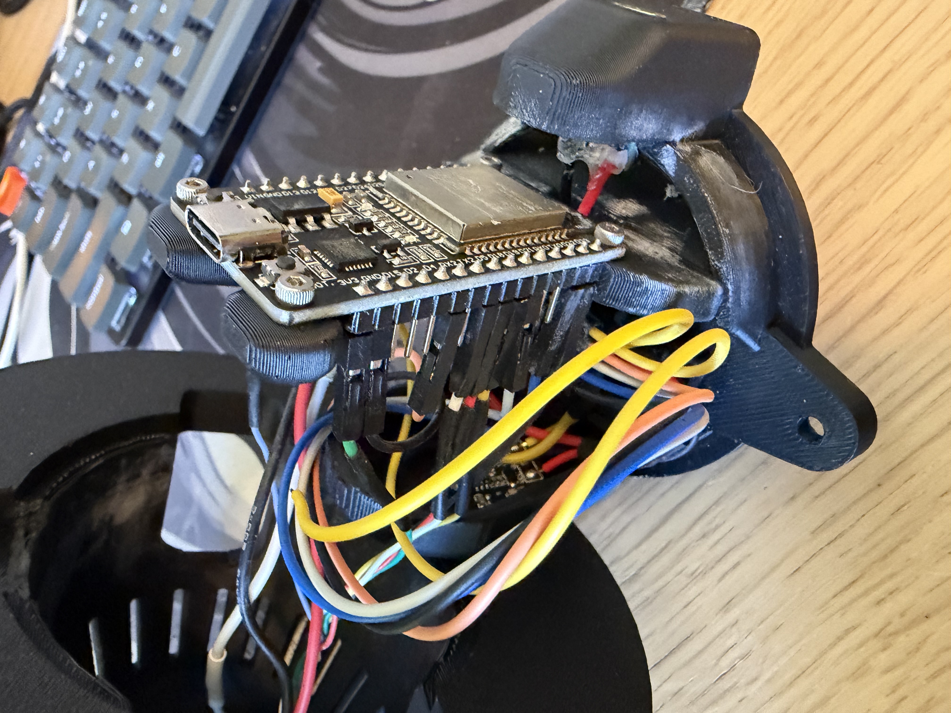
Before getting into firmware, I wanted to get the electronics off the bench and into something that actually resembled a real build. The concept design made it clear early on that there were going to be a lot of components crammed into a small footprint — ESP32, motor driver, buck converter, capacitive power switch, and all their associated wiring. Rather than let that turn into a rat’s nest, I designed a dedicated electronics capsule in SolidWorks to house everything cleanly.
The design is two-part: an inner electronics capsule that holds all the boards and wiring, and a cylindrical outer housing that fits over top of it and holds the motor on the upper face. The ESP32 sits upright in the capsule alongside the DRV8313 motor driver and the buck converter, with cutouts and mounting features to keep everything in position. The outer housing bolts over the capsule and gives the whole thing a clean, intentional look — it doesn’t look like a prototype, which was important to me.
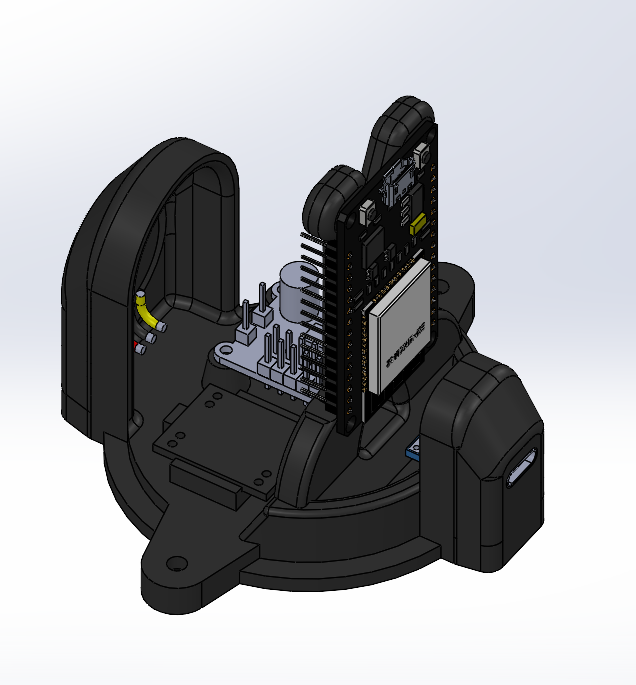
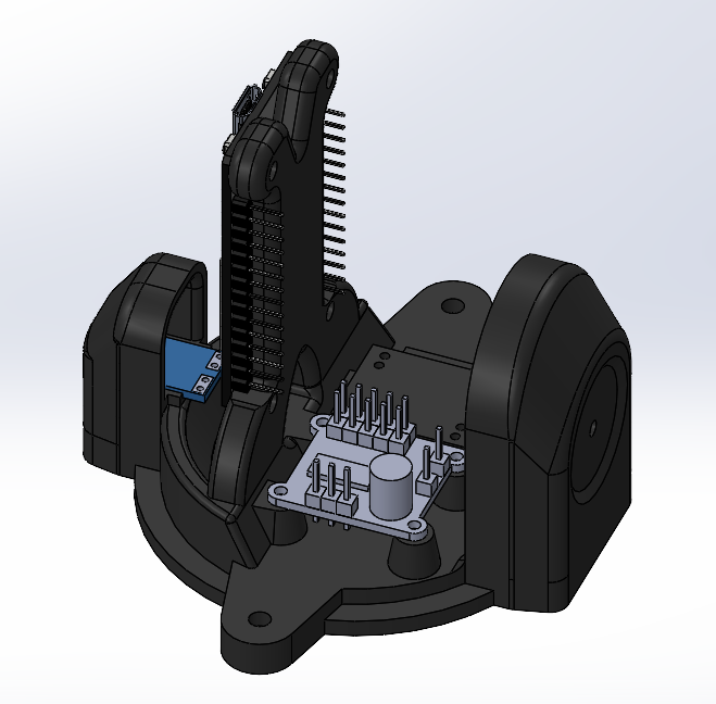
Getting this design right took some iteration. Fitting all the boards in a compact arrangement while still leaving room to actually connect wires is more of a puzzle than it sounds, and I had to think carefully about assembly order — some components need to go in before others because there’s no access afterward.
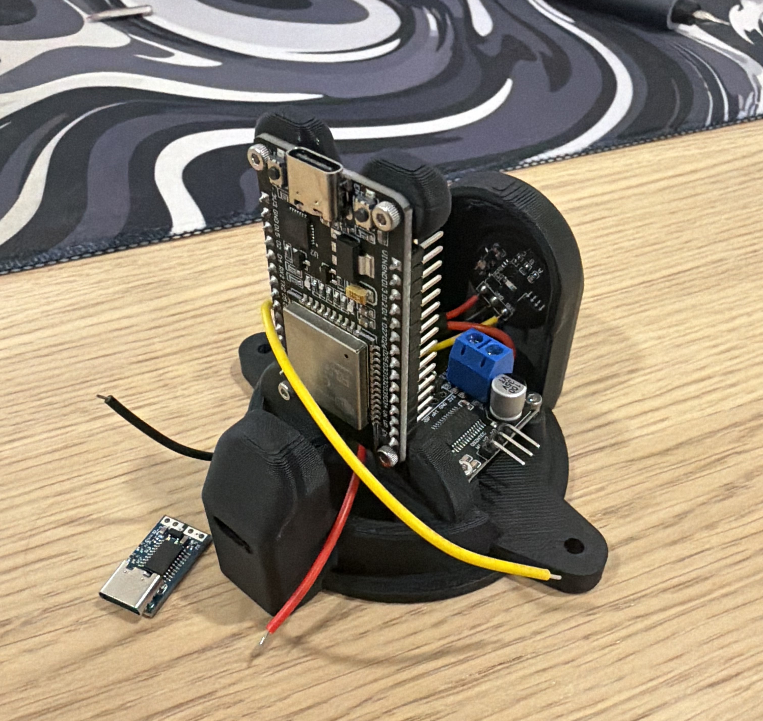
With the capsule printed and populated, I had the motor and driver wired up to the ESP32 for the first time. Before writing any closed-loop control code, I tested the motor under open-loop FOC — just commanding a rotating magnetic field at a fixed speed and letting the rotor follow it. When the motor spun up smoothly and quietly for the first time, that was a genuinely satisfying moment. Open-loop FOC is just the starting point, but getting a BLDC motor to spin correctly from scratch — with the SPI encoder reading back sensible data and the three phases commutating properly — is a real milestone.
Stage 3: Closed-Loop Motor Control — FOC From Scratch
With open-loop FOC confirmed working, the next step was closing the loop — adding position and velocity feedback to actually control where the motor goes, not just have it spin. This is where things got more involved.
I could have dropped in the SimpleFOC library for this and moved on, but I wanted to actually understand what was happening under the hood — so I kept the commutation implementation from scratch in C++.
The basic loop looks like this:
-
Read the rotor angle from the AS5048A magnetic encoder over SPI. The AS5048A gives 14-bit absolute angle data, and the firmware handles the full SPI transaction manually — constructing the read command, computing and verifying the parity bit, and masking the angle out of the 16-bit response.
-
Compute three-phase voltages. Given the electrical angle (rotor angle × number of pole pairs), the three phase voltages are sinusoidal functions offset 120° apart, scaled by the desired torque command. This is the heart of FOC.
-
Auto-calibrate on startup. On power-on, the firmware locks the rotor to a known position using a fixed voltage, waits for it to settle, reads the encoder, and stores that as the zero offset. Every subsequent angle reading gets corrected relative to this — without this step, the motor would fight itself every time it booted.
-
Drive the phases with PWM. The ESP32’s LEDC peripheral generates three 20kHz PWM signals at 10-bit resolution, one per phase. The phase voltages get mapped to duty cycles centered at 50% (midpoint = zero voltage).
Making the Angle Data Actually Useful
The raw encoder output had a small but visible sinusoidal error — a known quirk of magnetic encoders from imperfect magnet placement. I derived a harmonic correction function from calibration data and applied it in firmware, which cleaned up the velocity estimates nicely.
I also needed to handle the fact that the AS5048A wraps its output at every full rotation (0 → 2π → 0). For position control you need a continuous, unwrapped angle. The firmware tracks this by detecting the wrap-around jumps and accumulating an offset — simple in concept, annoying in practice if you miss an edge case.
Velocity Estimation
Velocity is computed the straightforward way: Δθ/Δt between loop iterations. The problem is that numerical differentiation is basically a noise amplifier, so a first-order low-pass filter (exponential moving average, 20ms time constant) is applied to keep the velocity estimate usable.
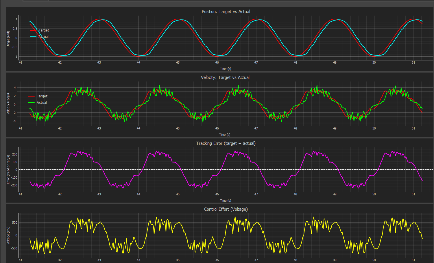
The Control Architecture
With a working angle signal, I put together a cascaded control loop:
-
Outer loop — Position PD controller (250Hz): Takes position error, applies proportional and derivative terms, outputs a velocity target. The derivative term uses the measured velocity rather than differentiating the error signal directly, which avoids “derivative kick” when the setpoint changes.
-
Inner loop — Velocity PI controller (500Hz): Closes the loop on velocity, with anti-windup clamping on the integrator and a feedforward term to reduce steady-state lag.
This architecture is textbook for servo drives, but implementing it from scratch taught me a lot of things that textbooks gloss over — timing interaction between the two loops, how aggressive you can make the inner loop before it destabilizes the outer one, and the practical difference between “works in theory” and “works on hardware.”
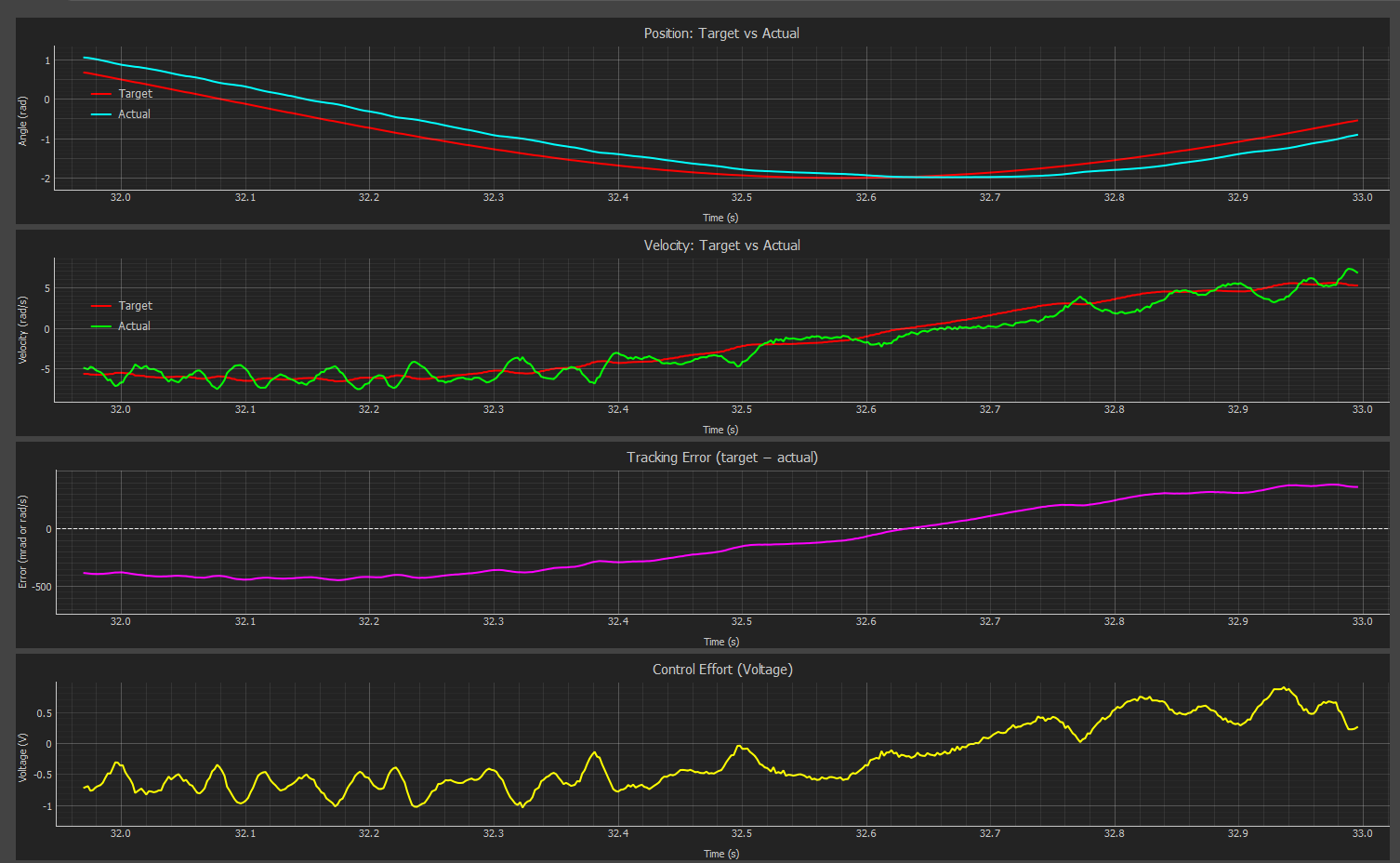
A Noise Mystery (Partially Solved)
During low-speed testing, there was a repeating speed ripple in the velocity feedback — even under a constant velocity command. I ran an FFT on the captured data and found a clear periodic component, but after systematically testing everything I could think of (encoder wiring, PWM frequency, angle correction parameters, varying speed), I couldn’t pin down the root cause definitively. It doesn’t meaningfully impact position control performance, so I made the call to move forward and revisit it if it causes problems with the balancing algorithm. Sometimes that’s just the right call.
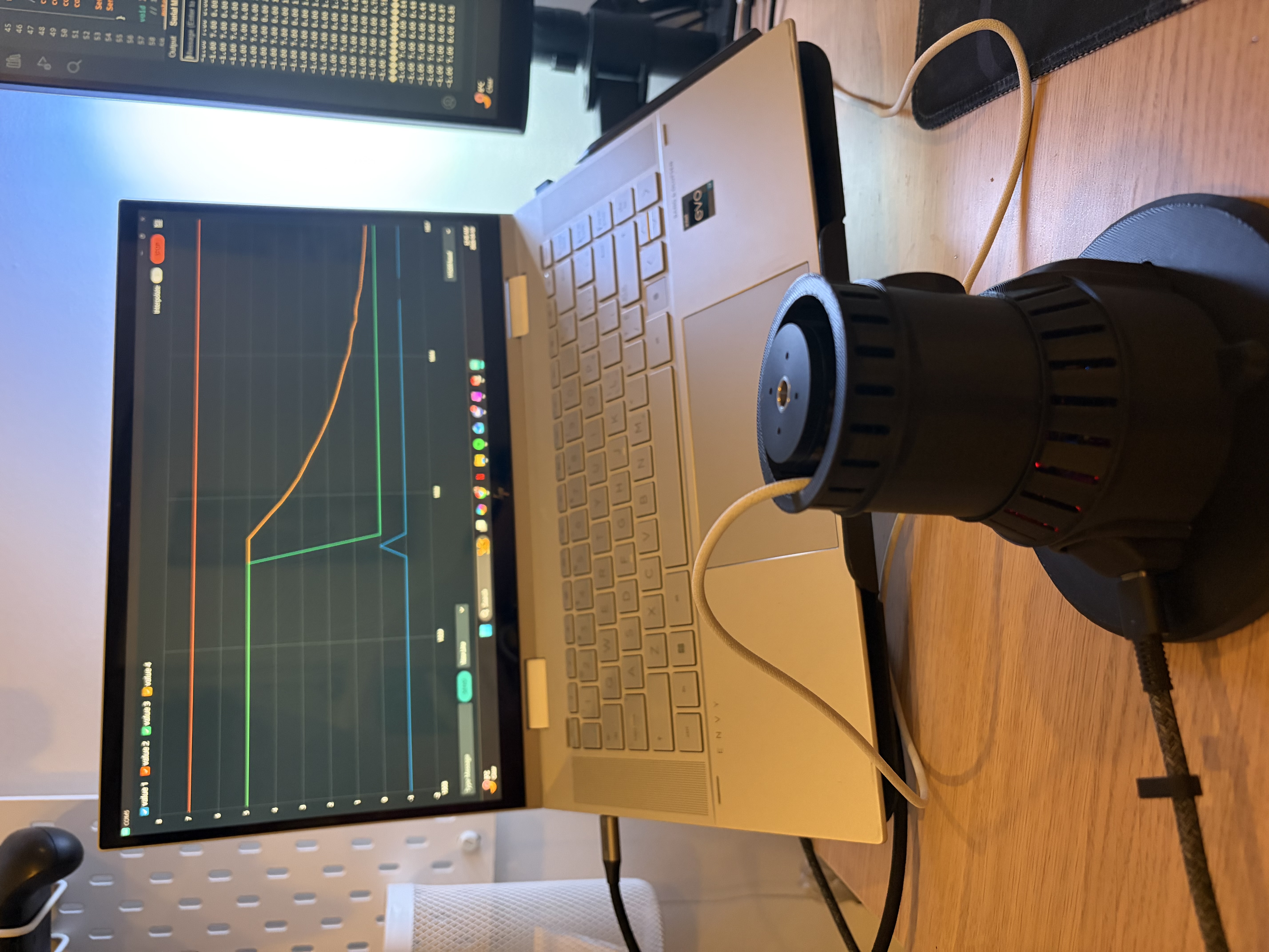
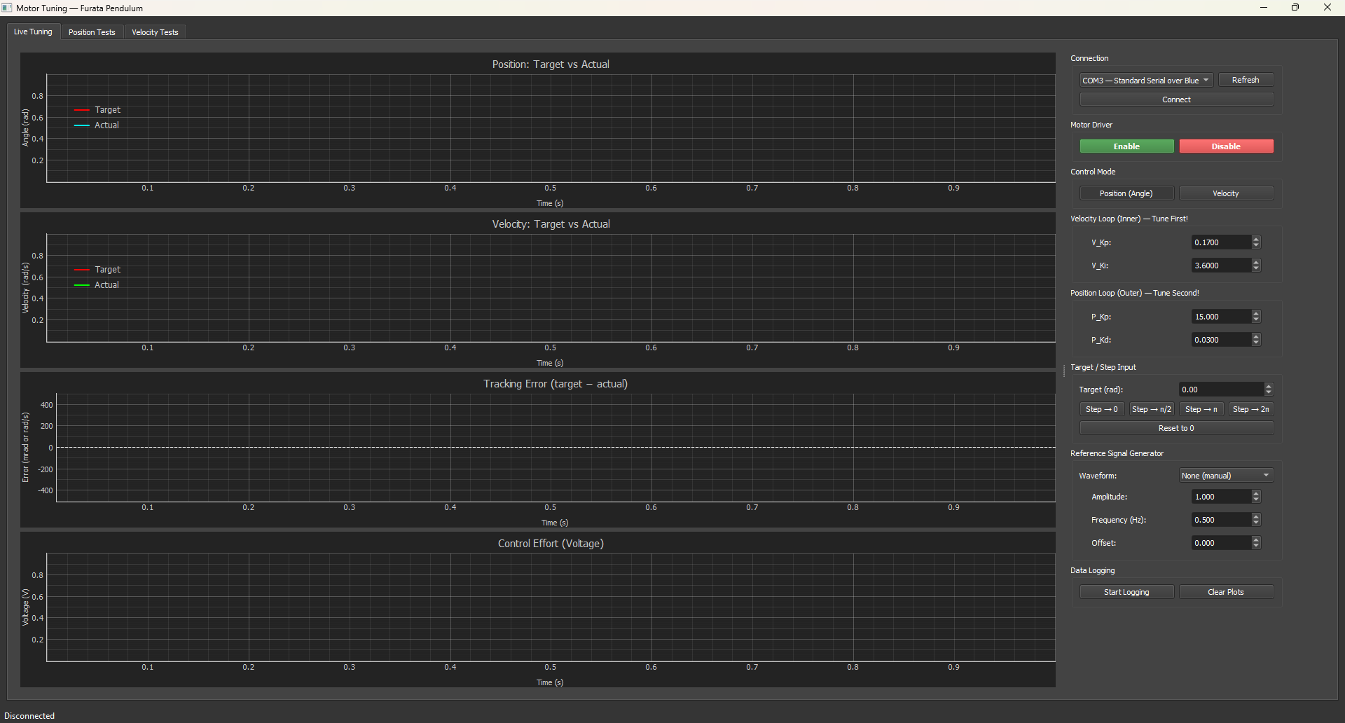
Stage 4: Building a Tuning GUI (Because Re-Flashing Gets Old Fast)
PID tuning by manually editing firmware constants, re-compiling, and re-flashing is exactly as tedious as it sounds. So I built a custom desktop GUI that talks to the ESP32 over Bluetooth serial at 460800 baud.
The GUI gives me:
- Real-time plots of position target, actual position, velocity target, actual velocity, and motor voltage — all live
- Live gain adjustment via sliders and input fields — change Kp, Kd, Ki on the fly without touching the firmware
- Built-in signal generator — command square wave, sine wave, or triangle wave targets at configurable frequency and amplitude, which is essential for characterizing how the system actually responds
- Mode switching between position and velocity control, plus a motor enable/disable toggle
On the firmware side, it’s a simple text-based command protocol — single-line strings like PP=50.0 to set position Kp, SG=Q to start a square wave. The ESP32 streams back CSV data at 50Hz.
Having this tool made tuning dramatically more efficient. Getting to see the step response update in real time as you drag a slider is a very different experience from the guess-and-flash loop.
Stage 5: Full Mechanical Design and 3D Printing
With the motor control working well on the bench, I went back to SolidWorks to finalize the full assembly design before printing anything.
The design had a few constraints that all had to play nicely together:
- Total height ≤ 220mm (my compactness target) while still housing the motor, both encoders, the slip ring, the electronics, and the power supply
- The slip ring needed proper housing — it passes the upper encoder’s SPI wires through the rotating joint without tangling
- Bearing seats needed to be press-fit, which means tolerancing matters
- Everything needed to be serviceable — I didn’t want to have to destroy the assembly to access the wiring
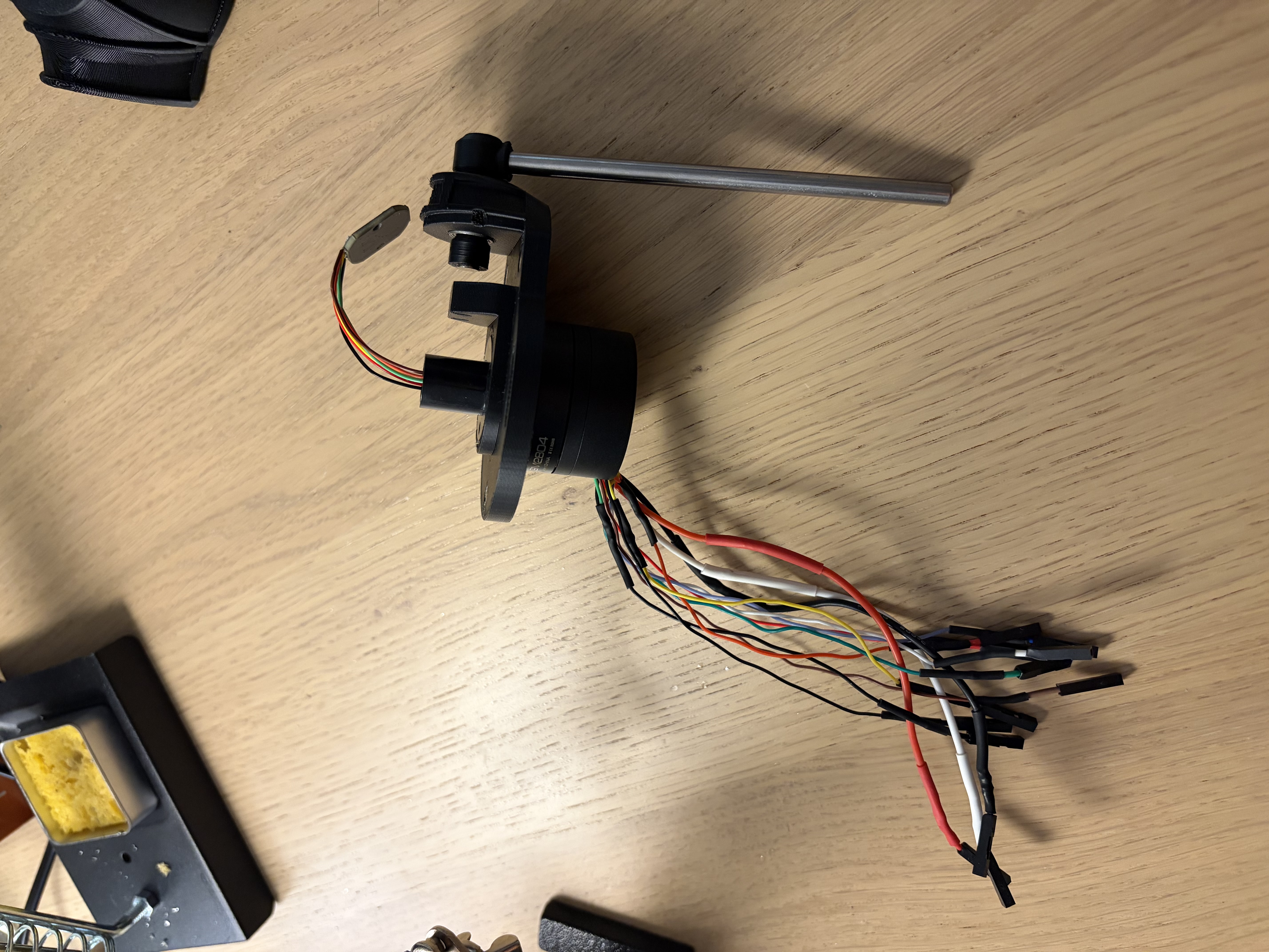
All non-COTS parts were custom designed: motor mount, base frame, slip ring housing, upper encoder bracket, and the pendulum arm. Standard 5mm steel rods serve as the pendulum body.
3D Printing: A Lesson in Tolerances
Parts were printed in PLA. The firmware side of this project had already taught me a few things — the mechanical side taught me that 3D printing tolerances are not something you can just ignore. Bearing press-fit seats in particular required a few iterations, because printed dimensions reliably deviate from nominal in ways that depend on your printer, filament, and print settings. The loop of print → test fit → adjust CAD → reprint is a real tolerance engineering exercise that doesn’t show up in any classroom project I’ve done.
Stage 6: Assembly and Wiring
Putting It Together
With parts printed and hardware on hand, it was time to actually assemble the thing. The assembly sequence had to be thought through carefully — bearings and the slip ring needed to go in before closing up the base structure, since there’s no getting to them afterward. M2 and M3 SHCS fasteners throughout.
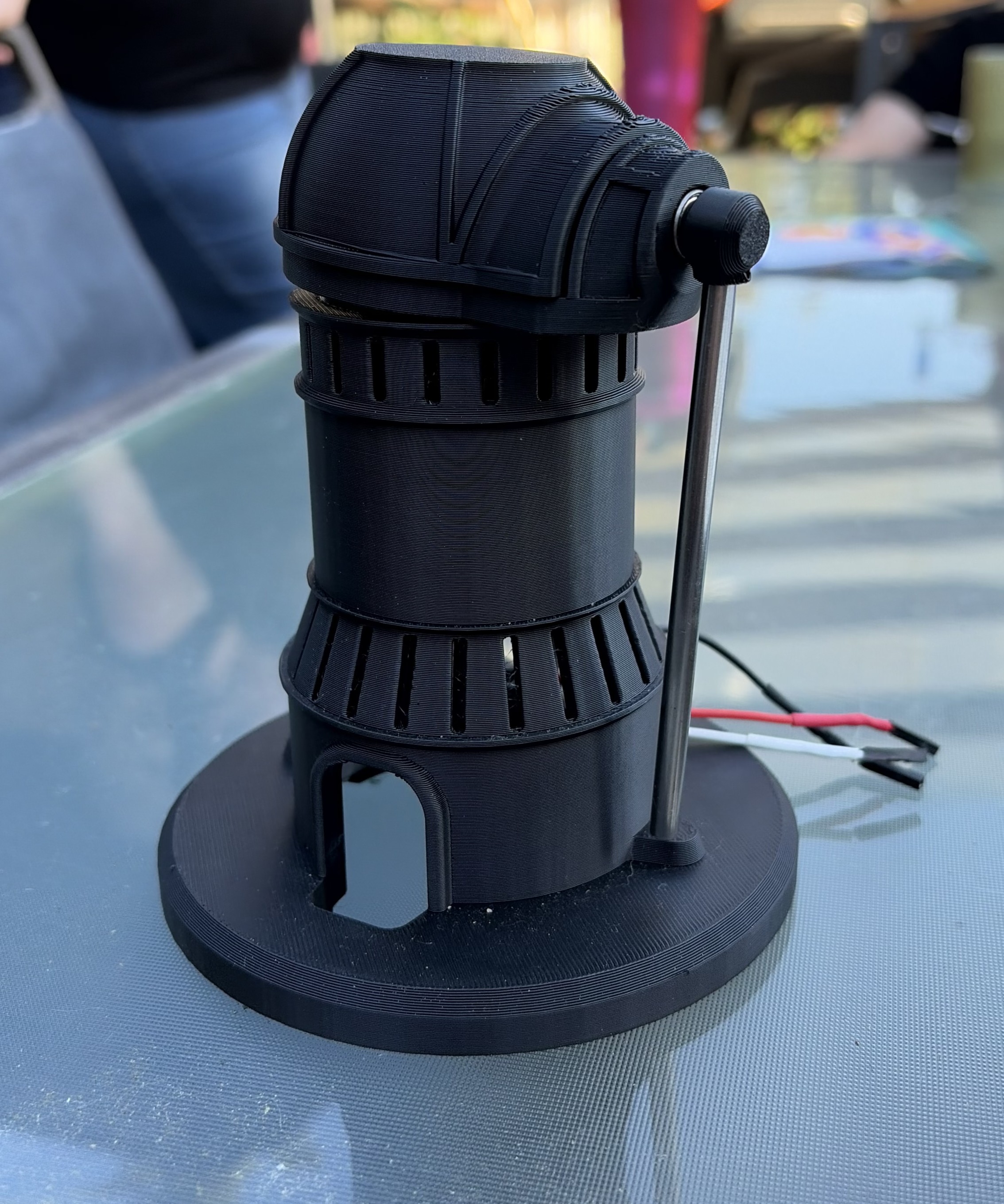
The Wiring — The Humbling Part
I’ll be honest: the wiring was the most time-consuming and occasionally frustrating part of this whole build. A few highlights:
The upper encoder solder joints were genuinely difficult. The AS5048A has 1mm-pitch surface pads — which is small enough that you’re working under magnification, holding your breath, and praying you don’t bridge two pads or lift one off the board. This is the kind of fine soldering skill that you can read about all you want, but the only way to actually get it is to do it a bunch of times.
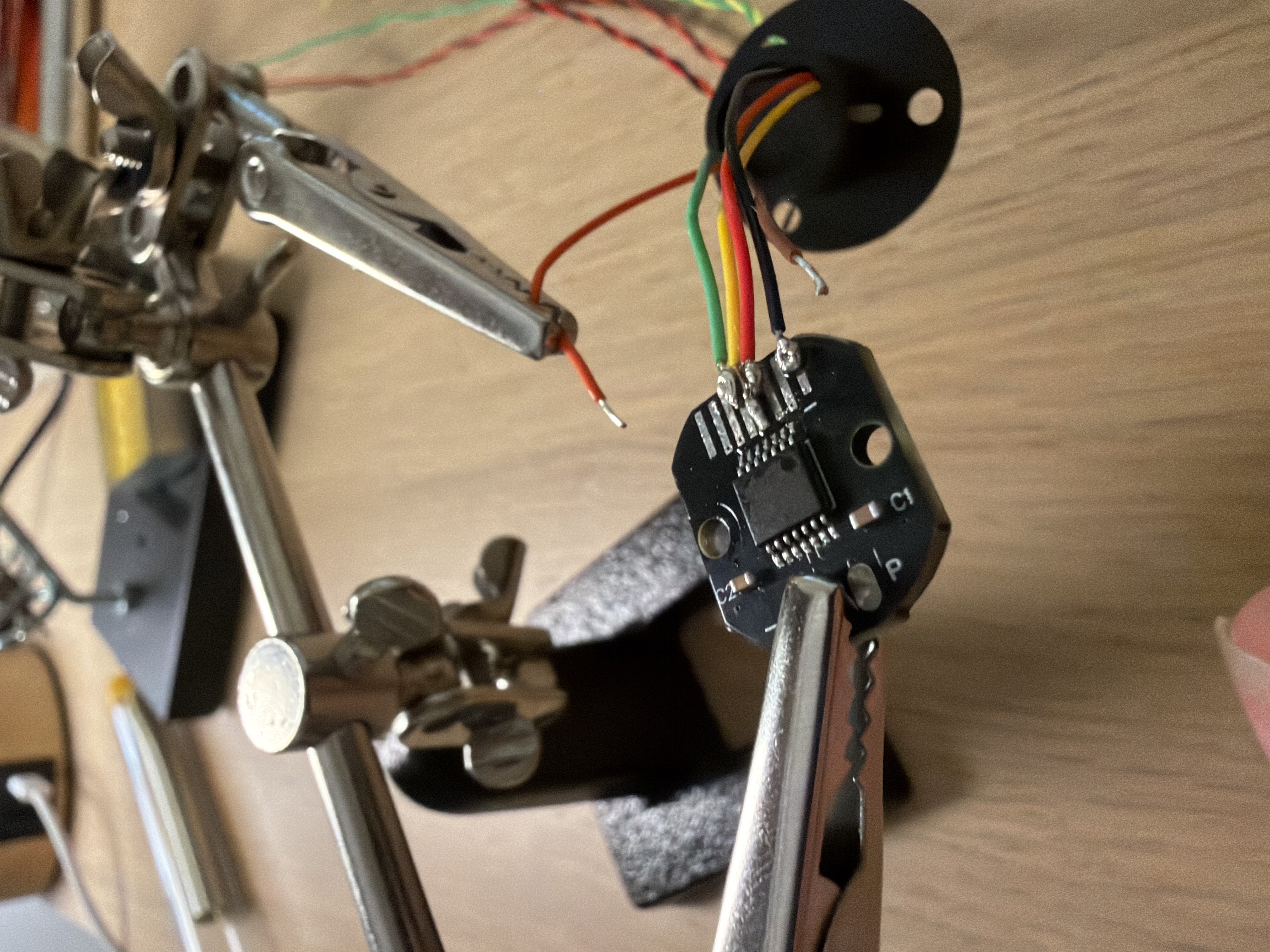
SPI bus wiring: Both encoders share the same SPI bus (MOSI, MISO, SCK) but have separate chip-select lines. The shared SPI wires were twisted and terminated with heat shrink; each CS line runs independently to the ESP32.
Connector system: All wires terminate in Dupont connectors that plug into the ESP32’s header pins. This kept things flexible during development — easy to re-wire when something needed changing. In hindsight, a proper connector block or even a simple custom PCB would have been tidier and more robust. That’s a “next project” lesson.
Stage 7: Power System and Dual-Encoder Validation
Both Encoders, Working at Once
After the full assembly, I extended the firmware to read both encoders simultaneously — the base encoder for FOC and motor control, and the upper pendulum encoder which the balancing algorithm will need. Both share the SPI bus, managed by toggling their respective chip-select pins. Got both reading sensible angle data at the same time. Small win, but a satisfying one.
The Power System Needed a Revision
The original design used a 3.3V buck converter to step down the 12V motor supply for the ESP32 and encoders. In testing, this caused two problems:
-
Bluetooth reliability. The ESP32’s radio performance degrades when VDD is marginal, and 3.3V with motor switching noise in the mix was enough to make Bluetooth serial unreliable.
-
Wrong input pin. The ESP32’s Vin pin is designed for 5V — it has an onboard LDO to step down to the 3.3V the core actually runs on. Feeding 3.3V into Vin works, but you’re using it outside its intended operating mode.
Swapping in a 5V buck converter fixed both issues. Bluetooth became reliable, and everything is now running in its intended operating range.
One Remaining Quirk
There’s a power-on reset issue where the ESP32 occasionally needs a manual reset button press to start executing after the power switch is toggled. The likely culprit is the EN pin not being held low long enough during the 5V regulator’s startup ramp, so the ESP32 starts before its supply is fully stable. An RC delay on the EN pin should fix it. It’s on the list.
Stage 8: What’s Next — The Part I’ve Been Building Toward
With the physical system assembled and motor control working well, the project moves into the control systems phase — which was the whole motivation for building this thing in the first place.
The plan is to approach it properly:
-
Derive the math. The Furuta pendulum is a two-DOF nonlinear system. I’ll work through the Lagrangian equations of motion to arrive at a state-space representation of the system dynamics.
-
Simulate in Simulink. Design and tune the control algorithm in simulation before deploying to hardware. The most likely approach is LQR for balancing, with an energy-based swing-up controller to get the pendulum to the upright position in the first place.
-
Validate on hardware. Compare the simulated response to actual behavior, iterate on the model and controller.
This is the stage I’ve been looking forward to the most — taking classical control theory from coursework and applying it to a real physical system that I built and understand from the ground up. More updates to come.