Smart Birdfeeder
I designed and built a solar powered birdfeeder equipped with a motion sensor, a camera, and a custom desktop app!

I decided to build a smart birdfeeder for my girlfriend’s birthday. She loves birds, and I love an excuse to learn new skills, so it seemed like the perfect match. My plan was ambitious: a fully 3D-printed structure, a Raspberry Pi "brain," and—the part that gave me the most grey hairs—integrated solar power.
Stage 1: Design and Material Choice
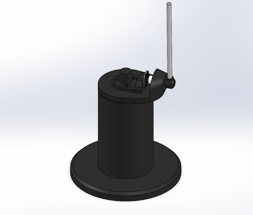
I started with a rough sketch and moved quickly into SolidWorks to build a preliminary reference design. I wanted a solid foundation, so I used a wood panel for the base and 3D-printed everything else on top.


Preliminary SolidWorks Concept, this was just a single part to get a feel for the size and form.
For the filament, I chose PETG. Most people start with PLA, but since this was going to live outside in the BC weather, I needed something that wouldn't warp under the sun or degrade in the rain.
The Roof: To fit on my print bed, I designed the roof in four quarters. I included custom-profiled cutouts to flush-mount two 3W solar panels I found on Amazon.
The Hopper: I designed a flap-and-silo system. You pour the seeds in through a flap on the back, and they gravity-feed into a front silo with a glass window so you can see the seed level.
Solving the Camera FOV Problem
This was the most complicated part of the mechanical design. Initially, I planned to put the camera above the seed silo. However, when I modeled the camera’s field of view in SolidWorks, I realized it couldn't see anything up close—it would just be a view of the bird's back at best.

The Solution: I decided to put the camera inside the silo. I designed a hollow "tunnel" that runs right through the middle of the seeds. This kept the camera dry and seed-free while giving it a front-row seat to the action.


Sourcing Parts and Electrical Issues
Sourcing parts was the hardest part of the project (this was before I discovered the magic of AliExpress). I chose a Raspberry Pi Zero 2W for the brain because of it's small form factor, low power consumption, and it has built-in Wi-Fi which will be essential.
The Camera
For the camera, I was looking at a few options that could be connected to the Raspberry Pi's camera port. I ended up going with the official Raspberry Pi Camera Module 3, specifically the wide angle version. This 12-megapixel camera is built around the Sony IMX708 sensor with a resolution of 4608 × 2592 pixels, and it also has powered autofocus.

The Power System:
- Two 18650 Lithium-ion batteries.
- An Uninterruptible Power Supply (UPS) module to allow simultaneous charging and discharging.
- A pair of 3W USB solar panels.
The Problem: I wanted to monitor the battery and solar voltage via an Analog-to-Digital Converter (ADC). But there was an incompatibility: the ADC needed to talk to the Pi at 3.3V logic, but the solar panels were pushing 6V and the batteries 4.2V.
Instead of waiting for a new part, I worked with what I had and designed a custom perfboard add-on with a simple voltage divider circuit (just a few resistors I soldered together) to scale those high voltages down to a safe 3.3V range. It worked perfectly!


The custom voltage divider board I made
Fabrication and Assembly
I was relatively new to 3D printing when I took this on, and this project was a marathon. Between the housing, the seed silo, and the roof, I spent about three straight days of printing and went through nearly 2kg of PETG filament.
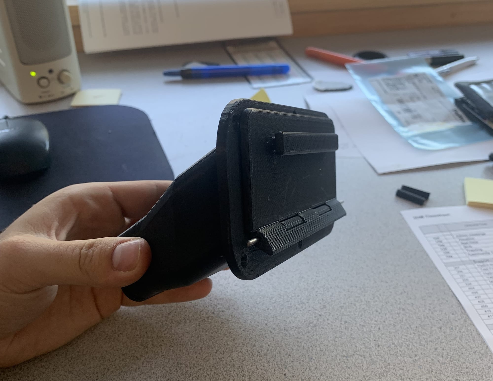
As the birthday deadline approached, it was a total scramble. I used brass threaded inserts for all the connections to ensure it was sturdy and used machine screws for assembly. Some parts warped slightly, but with some manual "persuasion", it finally came together.

Software
I’ll be the first to admit: I am primarily a mechanical guy, not a software developer. To get the IoT side working, I relied heavily on AI tools to help me write the Python scripts and build the app. However, I did still have to learn quite a lot and build the system framework on my own.
When all was said and done, ended up with a pretty cool system:
- Python/Pi:
- A script monitors a PIR motion sensor. When a bird arrives, it triggers an interrupt, snaps a photo, and sends it to Firebase (a cloud storage/database).
- Another script monitors the firebase database and checks for flags corresponding to commands from the app.
- Flutter App: I used flutter to build a custom app that pulls data from the cloud so we can manage settings, see battery levels, solar voltage, and a gallery of bird photos. I also integrated a live stream function!

Final Finish and Lessons Learned
For the final look, we primed and painted the feeder with acrylics and added a UV-resistant clear coat.

The Lesson:
If I did it again, I’d ditch the PIR motion sensor. They are a bit finicky and can false trigger. I’d look into a more reliable motion sensor or even try using the camera itself with some lightweight Computer Vision (CV) to detect movement instead.
I'd also look into a more efficient solar power system, while the solar system in this project ended up working well enough, it could be optimized for battery charging with a dedicated solar power module to integrate maximum power point tracking.
It’s currently winter, so the birds are lying low, but I’m stoked to see the first "customers" arrive this spring!